Short Circuit Testing with Multimeter – Step by Step
Short circuit testing with multimeter is a core skill every mobile technician must master. When a phone is dead, overheating, or instantly shutting down on charge, a shorted line is often the culprit. Below is a clear, practical, shop-tested guide to find and fix shorts safely and fast. 🧰🔍
—
🧠 What exactly is a short circuit?
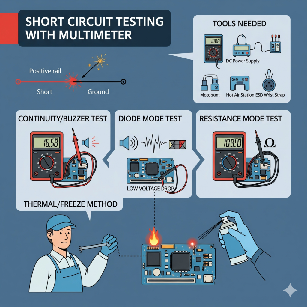
A short happens when a positive rail (VBAT / main power) unintentionally connects to ground (GND). Result: abnormally high current, heat, auto-restart, and sometimes a dead phone. Most common causes: shorted capacitors, damaged ICs, liquid ingress, wrong jumpers, or solder bridges.
—
🧰 Tools you’ll need
Digital multimeter (continuity + diode + resistance modes)
DC power supply (3.8–4.2 V, current limit 2–3 A)
Microscope or good magnifier
Flux, hot air station, soldering iron
Isopropyl alcohol (IPA) and soft brush
Freeze spray / thermal camera (optional but very helpful)
ESD strap + ESD mat (safety first!)
—
🛡️ Safety first (don’t skip!)
Remove the battery before board-level checks.
Work on an ESD-safe surface and wear a wrist strap.
Set DC supply to low voltage first (e.g., 1.0–1.5 V) with current limit.
Avoid overheating the board—use controlled temps and proper preheat.
—
🪛 Step-by-step: Multimeter methods that work
1) Continuity (Buzzer) Test 🔔
Goal: Quickly confirm if a main rail is shorted to ground.
1. Set multimeter to continuity (beep) mode.
2. Black probe on GND, red probe on the main power rail (e.g., big tantalum/ceramic caps near battery connector or PMIC).
3. Beep = continuity. If it beeps solidly between rail and ground, you likely have a short.
4. Repeat on sub-rails (charging line, backlight line, etc.) to narrow down the section.
> Tip: Some rails naturally show low impedance; use diode and resistance modes for confirmation.
—
2) Diode Mode (Forward Voltage Drop) 📉
Goal: Differentiate true short from naturally low readings.
1. Set meter to diode mode.
2. Black probe to GND, red probe to the test point/rail.
3. Healthy rails usually show 0.3–0.7 V (silicon junction range).
4. Reading ≈ 0.00 V or very low → likely hard short.
5. Reverse probes to compare both directions; strange symmetry often signals a shorted capacitor.
—
3) Resistance Mode (Ohms) 🧪
Goal: Compare resistance to ground to judge the severity.
1. Meter on Ω (ohms).
2. Measure from rail to GND.
3. Near 0–2 Ω → hard short. 10–50 Ω → leakage/partial short or a low-impedance rail (cross-check with diode mode).
> Pro move: Compare with a known-good board if available.
—
🔥 Localizing the short fast
4) Thermal/Freeze Method (with DC Supply)
Best real-world trick to spot the hot part.
1. Inject 1.0–1.5 V into the shorted rail at the battery pads (increase slowly if needed).
2. Watch the current draw; a steady high draw confirms the short.
3. Spray freeze spray over the area (or drip IPA).
4. The first component to thaw or evaporate alcohol = your hot/shorted part.
5. Usually it’s a ceramic capacitor near PMIC, charging IC, RF/PA sections, or backlight area.
—
🧩 Isolating sections (smart strategy)
If heat isn’t obvious:
Visually inspect under microscope for burned caps, solder bridges, or corrosion.
Lift one side of inductors/ferrites to isolate sub-rails (power distribution lines).
Remove suspect capacitors one by one on the hot line (start with the biggest caps closest to PMIC/IC).
If removing nearby passives doesn’t clear the short, suspect the IC on that rail (charging IC, PMIC, backlight IC, RF power amp, etc.).
—
🛠️ Repair actions (clean, remove, replace)
1. Ultrasonic/IPA clean liquid-damaged areas first; many shorts disappear after proper cleaning.
2. Remove shorted capacitor (most common). Re-test rail—if the short is gone, replace that cap.
3. If an IC is shorted, consider reballing (BGA) or replace it with a known-good part.
4. For solder bridges, wick the excess solder, add flux, and reflow cleanly.
5. After repair, power the board on DC supply and watch current behavior; then assemble and test with battery.
—
🧠 Pro tips (save time, save boards)
Always confirm with diode + resistance modes before pulling chips.
Don’t inject high voltage too early—start low to avoid collateral damage.
If multiple rails look short, go after the main VBAT/PP main first; many secondary shorts are symptoms.
Keep a small library of known-good readings (diode/ohms) for popular models—huge time saver.
Replace fake chargers/cables for customers; they’re short factories.
After fixing, run a thermal burn-in test: 10–15 minutes on DC supply and then in normal usage.
—
🧯 Common mistakes to avoid
Testing in continuity mode with battery connected (gives false results).
Overheating small components—use moderate airflow and temp.
Skipping cleaning after liquid damage.
Random jumpers without schematics—can create new shorts.
—
✅ Quick checklist (print & pin near your bench)
[ ] Battery removed, ESD on
[ ] Continuity test main rail → beep?
[ ] Diode mode confirmation
[ ] Inject low voltage → observe current
[ ] Freeze/IPA → find hot part
[ ] Remove suspect cap/IC → re-test
[ ] Clean, assemble, long test
—
🔚 Conclusion
Finding shorts isn’t guesswork—it’s a repeatable process. Use your multimeter smartly (continuity + diode + ohms), verify with DC power supply + thermal method, and isolate rails methodically. Most cases end up being a shorted ceramic capacitor; fix cleanly, test thoroughly, and educate the customer to avoid poor chargers and moisture exposure. That’s how you turn a dead board into a quick win. 💪🔧
—
📌 Meta Description (SEO)
Short circuit testing with multimeter explained step by step. Learn continuity, diode, and resistance methods, plus DC power supply + thermal tricks to find and fix shorts fast.
—
🔖 Tags
short circuit testing with multimeter, phone motherboard short fix, mobile short diagnosis guide, diode mode reading mobile repair, dc power supply short finding, how to locate shorted capacitor, pmic rail short solution, smartphone not turning on repair, continuity test mobile board, mobile repair troubleshooting steps